Mobility — component / DfAM
Footpeg — Stark Future
2026
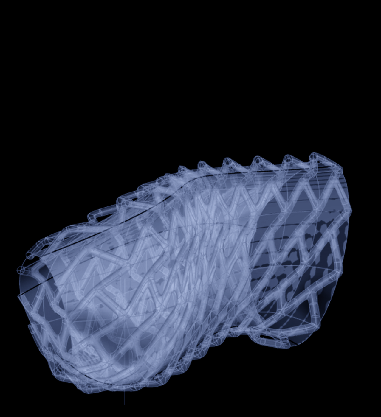
A titanium footpeg for the Stark Varg Skugga, redesigned to be longer and lighter without losing strength. Built in parametric CAD with topology optimisation and FEA, then set up for metal additive manufacturing.
Fixed interface, longer support, controlled geometry.
A parametric skeleton controls the critical dimensions: 160 mm length, 50 mm width, 5° inward tilt and 85° relative to the side plane of the motorcycle. The CAD work resolves the transition from the bike interface to a longer, lighter support surface.
The rib pattern comes from the load path.
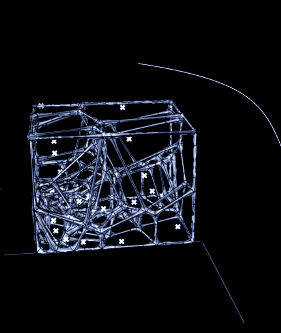
Two load cases mapped the structural behaviour: 5 kN at two-thirds of the support plus 5 kN frontal load; and 3 kN at one-third and two-thirds plus the same frontal load. Both studies pointed to a diagonal main rib with secondary reinforcement near the interface and tip. The final geometry reaches the minimum safety factor target of 1. Maximum von Mises stress appears around the interface and decreases through the rib network. Maximum displacement is located at the far tip and remains controlled at 3.43 mm.
Print orientation, build plate and jig close the loop.
Bambu Studio was used for rapid orientation studies, then nTop for support generation and build-volume distribution. The final orientation is 40° in X and 27° in Y, with an estimated 22.3 g of titanium supports per part. The jig fixes the printed part for repeatable machining of the spring-hole interface.
The result isn't only a lighter footpeg. It's the full route from a use case to a printable titanium part: parametric model, topology study, FEA, print setup. For me the route is as much the project as the part itself.